Spreader Beam Design Example
Spreader Bar Lifting Device Calculations And Design
Spreader Beam Design Spreadsheet Www Thenavalarch Com Youtube
Lifting Beam Design Calculations Fasrfilter

Spreader Beams Vs Lifting Beams Definitions Differences And Design
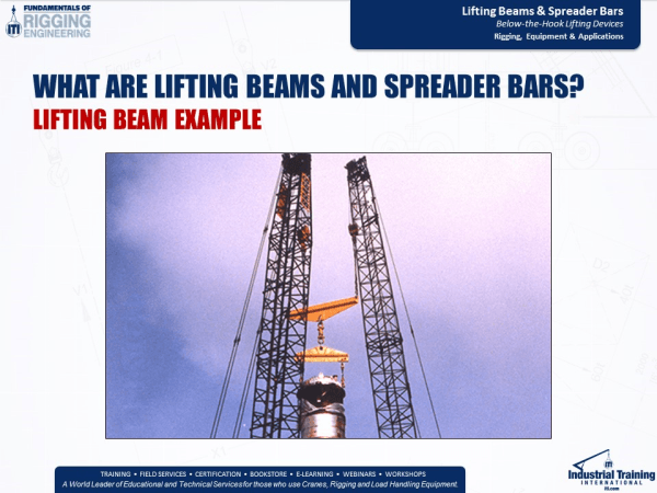
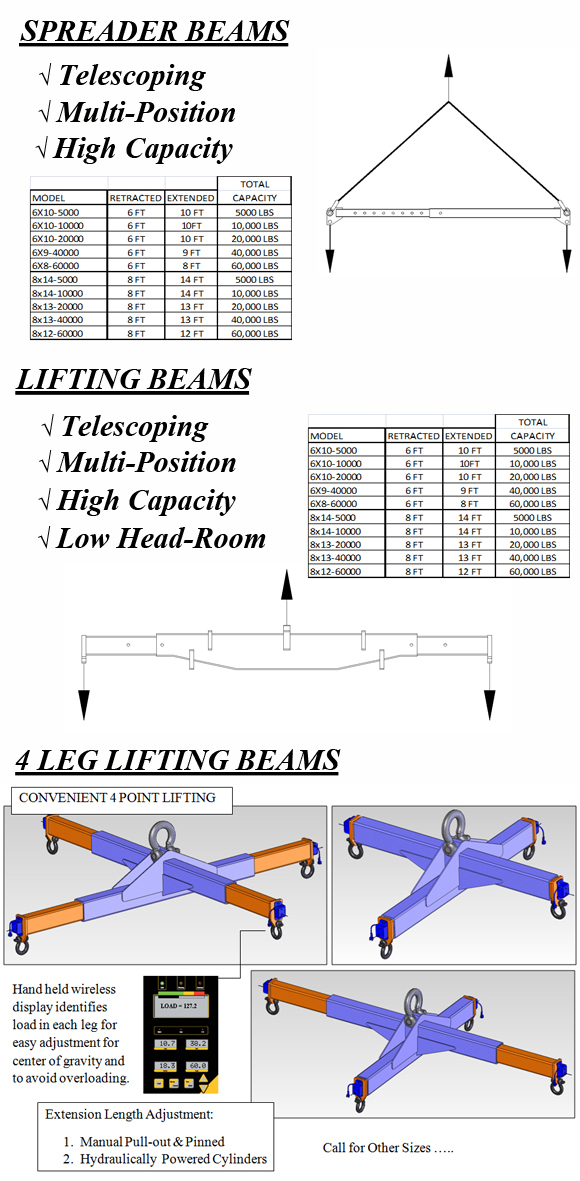
Lifting Beams

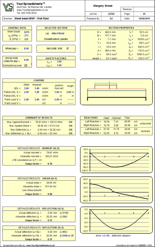
Spreader Beam Xls Structural Engineering Materials
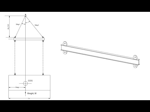
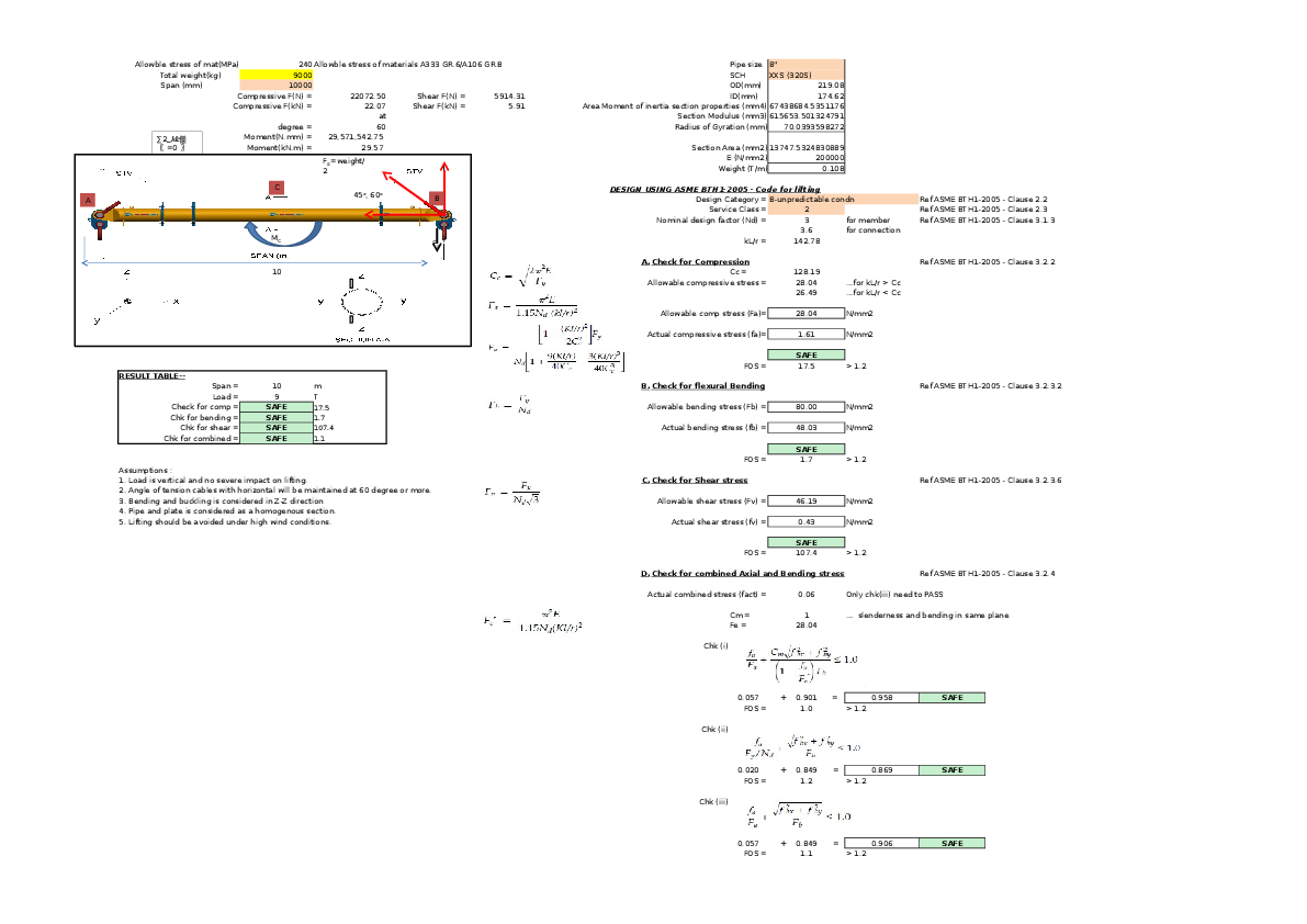
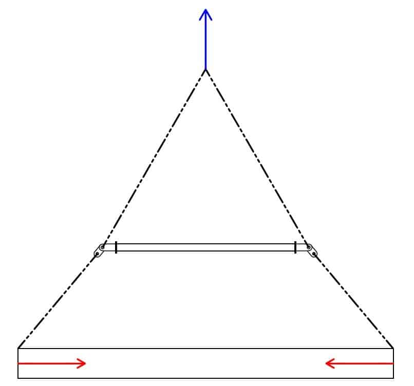
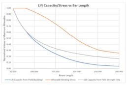
The typical approach to a spreader bar design looks like this.
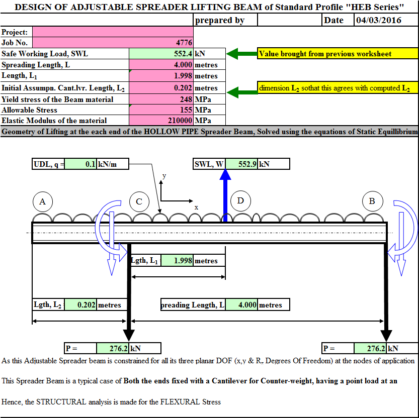
Spreader beam design example.

Leea Guidance The Verification Of Lifting Beams Liftingsafety
Http Data Conferenceworld In Dhruv 10july17 P666 679 Pdf
Xls Lifting Beam Calculation Rev 4 Best Sriraj S Varier Academia Edu

Spreader Beam Continuum Mechanics Civil Engineering

Calculating The Force On A Sling Load Connected To A Spreader Beam Youtube

Single Hook With Rectangle Spreader Beam Or Two Hooks 1a

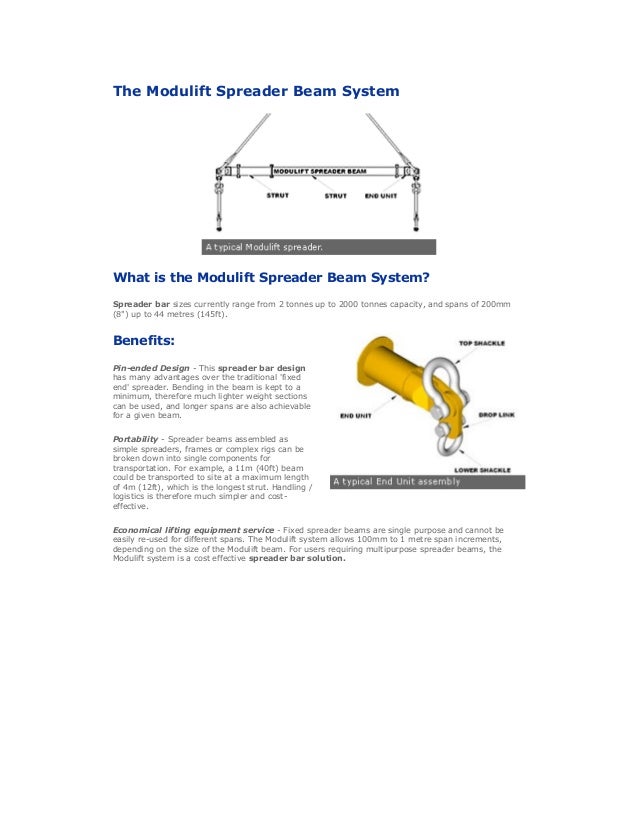
Spreader Beams Vs Lifting Beams

Designing A Spreader Beam For Lifting Thenavalarch

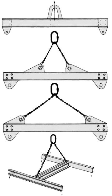
Spreader Beam Or Lifting Beam An Explanation For All

118784294 Lifting Beam Deign Staad 82187560 Design Calc 10t Spreader Beam Bending Beam Structure

Lifting Spreader Beams Southern International Professional Engineering Renderings

Spreader Beam Design Calculation Xls In 2020 Beams Design Cool Pictures

Lateral Torsional Buckling Of Suspended I Shape Lifting Beams Practice Periodical On Structural Design And Construction Vol 21 No 1

Lifting Lug Design V2 Xls Mes No Audio Youtube

Lifting Beam Design

Lifting Beam Design App Thenavalarch

Pdf Lifting Beams Calculation Tony Tay Academia Edu
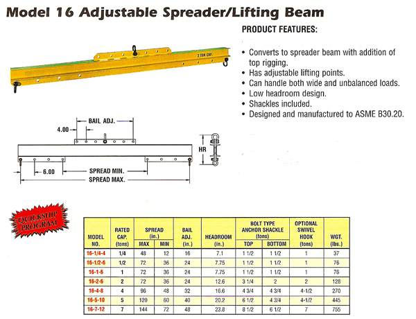
4 Point Lifting Beam Capacities And Sizes To Your Specification Range From 1000kg To 10 000kg Liftingsafety
Https Encrypted Tbn0 Gstatic Com Images Q Tbn 3aand9gcs3vik9rdxdvo Pzouzwkhnygpqyen0rjyivdmdzzqz Ify 85z Usqp Cau
Lifting Beam Spreader Bar Design 6 Quickies For Rigging Engineers
Balancim
Hybrid Electric Cranes

Guide To Lifting Beams And Lifting Spreaders Pages 1 34 Text Version Fliphtml5

H Frame Multi Purpose Lift Beam 140 X174
Misuse Of Spreader Beams Still An Issue Britlift Lifting Beams Spreader Beams And Frames
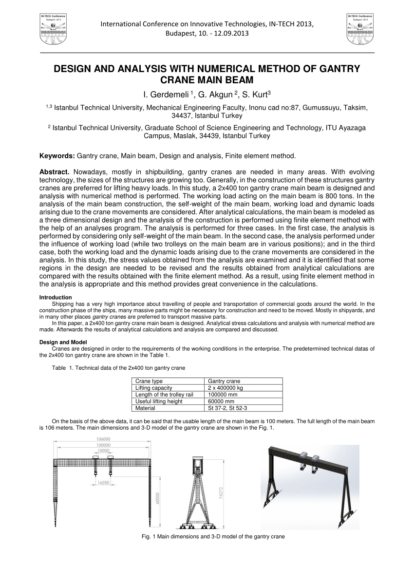
Pdf Design And Analysis With Numerical Method Of Gantry Crane Main Beam

Heavy Duty Spreader Beam Bar Beam For Saleclick Here For Spreader Bar Pricingwhat Is A Spreader Bar A Forklift Spreader Bar Is A Bar Spreader Bar Forklift Bar

How A Spreader Beam Can Reduce Horizontal Forces On A Sling Load Youtube

Lifting Beam Calculation
Https Www Nrc Gov Docs Ml0931 Ml093160469 Pdf

Guide To Lifting Beams Simplebooklet Com

Lifting Frames Britlift Lifting Beams Spreader Beams And Frames

Tandemloc Ad27001a 0s 1pa
Steel Spreadsheets

Pdf A Review On Lifting Beams

Lifting Design System Precise Design Automation Consultant

Design Of Stiffened Plate Lifting Beams Practice Periodical On Structural Design And Construction Vol 13 No 2

Crane Or Forklift Spreader Beams Amp Bars For Sale Spreader Bar Spreaders Forklift
Asme B30 20 Bth 1 Lifting Beams Basepoint Engineering

Misuse Of Spreader Beams Still An Issue

Spreader Beam Design Calculation Pdf
Https Rules Dnvgl Com Docs Pdf Dnvgl St 2016 05 Dnvgl St 0377 Pdf

Critial Lift Plan Overhead Crane Four Page Document Crane Lift How To Plan Crane
Https Encrypted Tbn0 Gstatic Com Images Q Tbn 3aand9gctjflxllehfdyfywy9ga32rockw 2odvkw2rwdc5guo7m0xqq7o Usqp Cau
Source : pinterest.com
